


A programmable logic controller (PLC) is an industrial solid-state computer that monitors inputs and outputs, and makes logic-based decisions for automated processes or machines.
PLCs were introduced in the late 1960s by inventor Richard Morley to provide the same functions as relay logic systems. Relay systems at the time tended to fail and create delays. Technicians then had to troubleshoot an entire wall of relays to fix the problem.
PLCs do have disadvantages. They do not perform well when handling complex data. When dealing with data that requires C++ or Visual Basic, computers are the controllers of choice. PLCs also cannot display data well, so external monitors are often required.
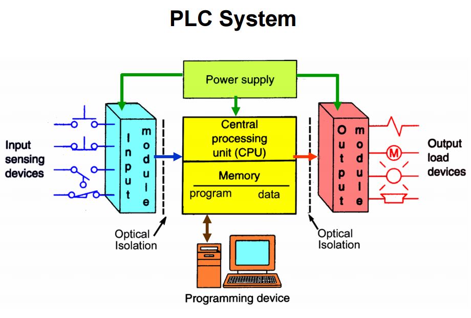
PLC Hardware Components
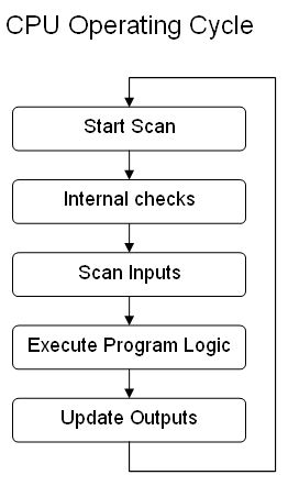
A central processing unit (CPU) serves as the brain of the PLC. It is a -16 or -32 bit microprocessor consisting of a memory chip and integrated circuits for control logic, monitoring, and communicating. The CPU directs the PLC to execute control instructions, communicate with other devices, carry out logic and arithmetic operations, and perform internal diagnostics. The CPU runs memory routines, constantly checking the PLC (PLC controller is redundant) to avoid programming errors and ensure the memory is undamaged.
Memory provides permanent storage to the operating system for data used by the CPU. The system’s read-only memory (ROM) stores data permanently for the operating system random access memory (RAM) stores status information for input and output devices, along with values for timers, counters, and internal devices. PLCs require a programming device, either a computer or console, to upload data onto the CPU.
PLCs read signals from different sensors and input devices. These input devices can be keyboards, switches, or sensors. Inputs can be either in digital or analog form. Robots and visual systems are intelligent devices that can send signals to PLC input modules. Output devices such as motors and solenoid valves complete the automated system.

Sinking and sourcing are two important terms when discussing input and output connections of PLCs. Sinking is the common ground line (-) and sourcing is the common VCC line (+). VCC stands for the positive supply voltage connection point. Sinking and sourcing inputs only conduct electricity in one direction. Each input has its own return line, and several inputs connect to one return line instead of several separate return lines. These common lines are labeled “COMM.” Sensor outputs mark the size of the signal given.
Direct current (dc) input modules connect to sourcing or sinking transistor type devices. Alternating current (ac) input modules are less common than dc inputs because most sensors have transistor outputs, so if the system uses a sensor input, it will most likely be dc; ac inputs take longer for PLCs to see compared to dc inputs. A typical ac input is a mechanical switch used for slow mechanical drives.
Relays are one of the most common output connections. A relay can switch ac or dc modules because they are non-polarized. A relay is slow, switching and settling at speeds of 5 to 50 milliseconds (ms), but can switch a large current. For example, a relay can be used for a low-voltage battery to switch a 230 volt AC main circuit. Transistor connections are faster than a relay and have a long lifespan. Transistors switch a small current, but only work with dc. An example of a high-power transistor has a current of 15 amps with a max voltage of 60V. Triac output (triode for alternating current) connections only control ac loads. Like a transistor, a triac is faster and handles large ac loads. A triac output, for example, can handle voltages of 500 to 800 with a current of 12 amps.
PLC Programming Language
Five programming languages are used in PLCs. They are defined by the international standard IEC 61131. Ladder logic is one of the most commonly used PLC languages. In it, symbols represent opening and closing relays, counters, timers, shift registers, and mathematical operations. The symbols are arranged into the desired program routine. Rules in ladder logic are termed “rungs.” Each rung has a single output, but a single input can be found in more than one rung.
Another programming language is function block diagram (FBD). It describes functions between input and output variables. The function, represented by blocks, connects input and output variables. FBD is useful in depicting algorithms and logic from interconnected controls systems.
Structured Text (ST) is a high-level language that uses sentence commands. In ST, programmers can use “if/then/else,” “SQRT,” or “repeat/until” statements to create programs.
Instruction list (IL) is a low-level language with functions and variables defined by a simple list. Program control is done by jump instructions and sub-routines with optional parameters
Sequential Function Chart (SFC) language is a method of programming complex control systems. It uses basic building blocks that run their own sub-routines. Program files are written in other programming languages. SFC divides large and complicated programming tasks into smaller and more manageable tasks.
PLC Communications
RS-232 is the most common method PLCs use to communicate with external devices. It is a serial communication standard that uses binary code to transmit data in American Standard Code of Information Interchange (ASCII) format. ASCII translates letters and numbers into binary code that computers can read. ASCII is a 7-bit code (a bit being “1” or “0”) that, when translated, results in 128 characters. PLC serial ports transmit and receive data as voltages. PLCs can be either data terminal equipment (DTE) or data communications equipment (DCE). A DTE, for example, can be a computer, while a modem is a DCE. Typically, PLCs are DTEs and external devices are DCEs. When the PLC and the external device connected to it are the same equipment (i.e., DTE/DTE or DCE/DCE), they cannot communicate with each other and a null-modem connection must be used.
Subscribe to:
Post Comments (Atom)


No comments:
Post a Comment